Murphy Bed

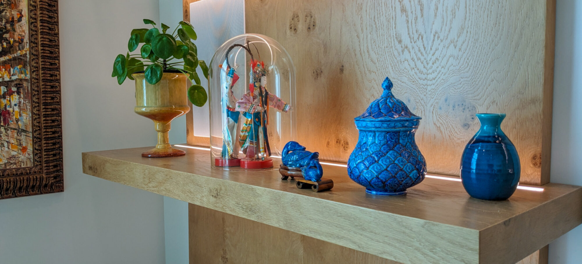
Yesterday we installed the Murphy Bed. It is built from rustic alder. The bed is a queen size bed. The cabinets on either side of the bed have a hand-carved counter top with LED lights illuminating them.

There are four sets of LED lights, one above each countertop, one above the bed shining down and a fourth set above the cabinetry. All the lights are dimmable and are controlled by a remote with each set on a separate channel so they can be activated independently.

Raising and lowering the bed is very easy, as the spring mechanism balances the weight of the bed panel and mattress.

It was impressive, despite the amount of cabinetry, how much the installation of the Murphy Bed opened up the room.

Study Unit

I installed my latest project yesterday, a study unit. It is built from rustic alder. The desktop is solid alder and has a carved live edge.

The study unit includes LED lighting above and below the cabinets illuminating the desktop and the room. The lighting is dimmable and is controlled by a remote. The desktop includes two low profile pop up power/data outlets. They each have two USB ports and two 110v outlets.

The drawer boxes are solid maple with dovetails and there are four cabinets for hanging file folders. There is also a roll out drawer for the paper shredder. The drawer guides are full extension under mount guides. The door hinges are soft close.

From my client’s initial sketch I designed the project in eCabinets. I was then able to show my client photo realistic renderings for their approval prior to starting the project.

Split Turned Legs

I am building a custom vanity cabinet.  The design features a couple pairs of split turned legs either side of each door opening.   I thought I would take the opportunity to document the process involved in creating a split turning.  Split turnings are typically used in furniture and architectural applications, as decorative elements.  The process has other applications in woodturning, including the “Lost Wood Process”.

The Merrimam-Webster dictionary definition is as follows:

 a turning (as of a baluster) split vertically and applied decoratively (as to the surface of a chest or cupboard) or used as a spindle in a chairback

Dompkowski - Vanity (shaded(


Essentially the process involves gluing two pieces of wood together with a piece of paper sandwiched between them.  The piece is then mounted on the lathe and turned to the desired shape.  Once the turning is complete the paper joint is split using a chisel, the paper literally splits in half, yielding two identical half turnings.  A simple process, but there are a couple of important things to watch out for.

Dompkowski - leg

The design of the split legs I needed is fairly simple.  It is a cone, approximately 32″ long, tapering from 3″ diameter to 1″ diameter.  I started with a couple pieces of 8/4 maple, about 6 1/2″ wide and 33″ long.  One face was flattened at the jointer.  Just as with any glue joint, it is important to have the two mating surfaces flat.

IMG_1082

The piece was then ripped in half at the table saw, yielding two pieces of 8/4 maple, each 3 1/4″ x 33″.

IMG_1083

The only paper that I have personal experience using is the brown builders/construction paper.  It is available from the home improvement retail stores and is typically used as a paint drop or to protect new flooring from damage by subsequent trades.  It is a fairly thick paper, probably a little thicker than a brown paper bag.  I’ve read that you can use newsprint or a brown paper bag, but I don’t have any experience with that.

IMG_1084

In order to have a successful and stress free glue I’ve learnt that you need to get everything prepared in advance.  As well as clamps, glue and spreaders, this also involves cutting the paper to size.  I also like to fold the paper over the edges of the wood so that it is easier to place in the correct position once the glue is applied.

IMG_1085

It is very important to note that you are gluing the paper to both pieces of wood, so you need to apply the glue to both pieces of wood.  If you think of it in terms of a sandwich analogy, where the two pieces of wood are the slices of bread, and the paper is the meat in the sandwich, you need to put the mayo (glue) on both slices of bread! 🙂

IMG_1086

Once the glue is applied to both pieces of wood, place the paper over one of the pieces …

IMG_1087

… then place the other piece of wood on the paper, and clamp together.  I like to leave the assembly clamped overnight.  The glued up blank now measures approx. 3 1/4″ x 3 1/4″ x 32″.

IMG_1088

After removing the clamps, I clean up the ends of the blanks at the miter saw and mark the centers of each blank.  Actually, the one center line is already determined by the glue join, I just mark the other line.  When placing the blank on the lathe it is very important to position the centers accurately at the head stock and tail stock.  The center determined by the glue line is actually more important than the other center line.  If the glue line is not placed directly on center, then the two pieces once split will not be identical.

IMG_1089

I like to use a steb or safety center at the head stock.  This enables me to turn a bit more aggressively with out worrying about damaging the piece if I get a catch.

IMG_1090

At the tail stock I use a cup live center.  It is VERY important to use a cup center at the tail stock.  If you use a cone center then you will split the two pieces apart as you tighten up the tail stock.

IMG_1091

The turning on this design was not very complicated.  As I mentioned before, it was a straight taper from 3″ diameter to 1″ diameter.  However, it can be challenging to achieve a perfectly straight taper.   In order to determine some guide points I drew out the leg design life size on a piece of construction paper.  I was now able to use this drawing to determine the diameter of the finished leg at five intermediate points evenly spaced along the leg.

IMG_1092

Once the piece was turned round, I marked the points along the leg …

IMG_1095

… and using a parting tool and a pair of calipers, established the correct diameter at each of those points.

IMG_1096


IMG_1097

Use a spindle roughing gouge I then turned the leg just a bit bigger than the final diameters.

IMG_1098

The final diameter and taper was established using a 1 1/4″ skew chisel.

IMG_1100

In order to further smooth and straighten the taper I use the following trick.  First, with the lathe running slowly, I draw a pencil spiral down the length of the leg.

IMG_1106

I then attach a piece of 120 grit sandpaper to a piece of plywood with some spray adhesive.  I run this up and down the leg as it is turning slowly.

IMG_1108

Wherever the pencil marks are sanding off indicates a high point.  So I am then able to refine those high spots with the skew.

IMG_1109

The piece is now sanded smooth.

IMG_1110

The moment of truth arrives!  Time to split the turning.  This is done by placing a sharp chisel directly on the paper glue joint and gently driving it into the joint with a hammer.

IMG_1112

It is a little slow to start …

IMG_1114

… but once the split is started the two pieces separate very easily.  Actually, it is always a bit disconcerting as to how easily they come apart, considering that a short while ago they were spinning rapidly on the lathe!

IMG_1115

A couple images of the pair of split turned legs.  The paper still needs to be removed.  This can be done with sandpaper, although depending on the size of the piece I will often make a shallow pass over the jointer to remove the paper.

IMG_1117


IMG_1121

Wooden Collar with Threaded Pewter Insert

In this post I’m going to share my technique for making a wooden collar for a hollow form with a threaded pewter insert.  In previous posts I have shown how I cast, turn and thread a pewter collar for a hollow form.  I’ve also shown an easy way to cast a texture onto a pewter collar for a hollow form.   Aesthetically, the main difference with this collar is that when the finial is screwed into the collar there is no pewter showing, however I am still able to retain the functionality of the threaded pewter.  It is a nice way to showcase a special piece of wood on the top of a hollow form.

IMG_0862

In this example I am using a small piece of rosewood burl.  It is about 3/4″ thick and I have cut it into a rough circle about 2 1/2″ diameter on my bandsaw.  With the jaws of my chuck closed I am holding it against the jaws with the live center.

IMG_0863

This enables me to round it over and turn a shallow dovetail tenon on the piece.IMG_0864

I then rotate the piece and mount it in the chuck jaws so that I can drill a 1″ hole with a forstener bit to a depth of about 1/2″.

IMG_0865

Using a thin shop made parting tool I then cut a groove into the wall of the hole that I have drilled.  The idea here is to form a shallow groove to make a mechanical joint for the pewter.  The parting tool was made from an old sawzall blade.

IMG_0866

Here you can see the groove.  It is about 1/8″ deep.  I find it easiest to stand on the far side of the lathe when turning this groove.

IMG_0868

The piece is then taken to my melting pot and molten pewter is cast into the hole.  When the pewter has cooled it is a good idea to wick some thin CA glue into the joint between the pewter and the wood.  The groove provides a mechanical joint that prevents the pewter from coming out of the hole.  However the forces involved in drilling and threading the pewter are likely to cause the pewter insert to spin in the hole.  Applying the CA glue at this point will prevent this from occurring and any CA residue will be turning off later in the process.

IMG_0869

The piece is mounted back on the lathe and a 3/4″ hole is drilled through the piece.  IMG_0870

Using a lathe tap holder, the threads are tapped into the pewter.  As you can see I forgot to wick the CA glue into the joint between the pewter and the wood.  The pewter stayed fixed while I was drilling, but as soon as I started threading it started to rotate.  you can clearly see the CA residue on the surface of the wood which I will turn off shortly.

IMG_0871

A close up shot of the tap and the threaded insert.IMG_0872

The top surface of the collar is now turned and a seal coat of shellac applied.
IMG_0873

A 1/2″ male adapter is now mounted in a pair of long jaws and the collar is turned around and screwed onto the adapter to allow me to finish the underside of the collar.

IMG_0874

Another shot showing the collar held on the lathe with the PVC male adapter.IMG_0875

The underside of the collar is turned.  A tenon is turned to allow it to be attached to the opening in the hollow form.  The bulk of the collar is also reduced, as is the threaded pewter insert, while still leaving some threads to accept the finial.
IMG_0876

A shot of the top surface of the finished collar.IMG_0877

A shot of the underside of the finished collar.

PVC Gouge Handle with Aluminum Insert

I buy my bowl and detail gouges from Thompson Tools.   They come unhandled and I have always turned wooden handles for them.  I enjoy the process of turning a handle for a tool that I will be using for a number of years. However, as I have started to travel more for demonstrations, I’ve found that it is pretty challenging to pack long handled gouges.  So I decided to make some new handles for my bowl and detail gouges.

A couple of years ago I saw Mark St. Ledger demonstrate at the Florida Woodturning Symposium.   As well as thoroughly enjoying his demonstration, I remembered the handles he was using on his gouges.  I’m not sure what he was using as an insert, but I do remember that the handle was made from PVC pipe.  I decided to see if I could make something similar.

I ordered a length of 1 3/8″ aluminum round bar and also brought some 1″ Schedule 40 PVC.  I chose the Schedule 40 over the other variety they had in the big box store as the Schedule 40 had thicker walls.

IMG_0811

The first step was to cut the aluminum round bar into 2 1/2″ lengths.  I did this using a v-block on my bandsaw.

IMG_0812

I then mounted the length of aluminum round bar on my lathe using the long jaws of my chuck and drilled it.  I find that I get more accurate results if I drill the hole out in increments of about 1/8″ diameter.  On this particular insert I needed a hole of 1/2″ diameter.  So I first drilled a 3/8″ diameter hole …

IMG_0813

… and then drilled the 1/2″ diameter.  I also used a bit of oil to lubricate the bit.  The hole was drilled all the way through the aluminum round bar.

IMG_0814

Without removing the round bar from the long jaws, the next step was to face off the aluminum using a detail gouge.

IMG_0815

I then turned a 1 1/2″ long tenon to match the internal diameter of the PVC pipe, approximately 1″.

IMG_0816

IMG_0817

A test fit to make sure that I had a snug fit and PVC butted square up to the shoulder of the tenon.

IMG_0818

I then supported the PVC pipe using a 60 degree live center in the tail stock.IMG_0819

I turned the section of the round bar up to the chuck jaws down to match the external diameter of the PVC pipe.
IMG_0820

I then sanded the PVC pipe using 80 grit to get rid of the lettering on the pipe, and then worked my way through the grits ending at 180.  This left a surface that felt good, relatively smooth with a bit of texture.

IMG_0821

I reversed the round bar in the chuck jaws … IMG_0822

… and finished turning the nose of the insert.IMG_0823

Moving to the drill press I drilled a hole in the insert.  I held the insert steady using a v-groove block while I was drilling.

IMG_0824

I then tapped the hole with a 1/4 – 20 thread.IMG_0825

Finally, I mounted the insert back on the lathe and just cleaned up the inside of the hole again.

IMG_0826

Completed sanding the insert and a bit of polish.  All shiney 🙂
IMG_0827

The next step was to make a hardwood plug for the other end of the handle.  I chose to make this from African Mahogany, firstly because I wanted to include some wood in the handle, but also because at this stage I was pretty tired of turning aluminum.  The steps to make the end plug were exactly the same as for the aluminum insert with the exception of all the drilling and tapping.

IMG_0828

IMG_0829

IMG_0830

IMG_0831

IMG_0832

Once the hardwood plugs were made I expoxied them and the aluminum inserts into the PVC pipes, and gave the handles a couple coats of matt lacquer. IMG_0833

Hero shot of  the completed set of handles!IMG_0834

The African Mahogany plugs.  They look great against the white PVC.
IMG_0837

The business end of the handles showing the aluminum inserts with socket set screw.


Modification to an Étagère

I received a commission recently from a designer.  Her clients had an Étagère which they were not happy with.  The piece was too tall for the room in which they had it displayed and so they wanted to know if it was possible to cut it down.  I met with them and the designer and we decided that the modification was possible.  The goal was to re-size the piece, while making the joints near invisible and also maintain the structural integrity of the piece.

From Wikipedia: 

An étagère is a piece of light furniture which was extensively made in France during the latter part of the 18th century. It consists of a series of stages or shelves for the reception of ornaments or other small articles. Like the what-not it was very often corner wise in shape, and the best Louis XVI examples in exotic woods are exceedingly graceful and elegant.


As you can see from the image below the piece was very tall, 88″.
IMG_0656

My initial thought was to make a cut below the second lowest shelf and then move the feet to the underside of that shelf.  From the standpoint of hiding the joint that would have been the simplest way.  However there were a couple of details on the upright just above the bottom shelf which needed to be preserved, so it was decided that each upright needed to be cut in two places, once just below the third lowest shelf and once just below the second lowest shelf.   Then the second lowest shelf would be discarded and the lowest shelf moved up one section.

IMG_0657

In theory it was a very simple plan.  Eight cuts and then glue it back together.  In practice it required a lot of thought, problem solving and attention to detail in order to accomplish the cuts and then rejoining the pieces, all while achieving the goal of invisible joints and maintaining the structural integrity of the piece.

Once I got the piece to my workshop, I set it aside for a couple of days while I thought carefully about each step.  The photo essay below shows how I went about making the modification.

I opted to make the cuts using a flush cut saw.  I could see no way to make the cuts cleanly and safely using a power saw of any sort.  While a power saw can make a quick cut, in this situation I just saw to much potential for things to go horribly wrong really quickly.  The first step was to tape around each upright piece to support the wood fibers as much as possible during the cut and ensure a clean cut with little to no tear out.  I also taped some pieces of Formica to the underside of the shelf so that the saw did not scratch that surface.  I needed to make the cut as close as possible to the underside of the shelf in order to maintain the length of the upright piece.  The thin kerf of the flush cut saw would also help achieve that goal.

IMG_0659

The Étagère is an expensive and beautiful piece of furniture, so needless to say the first cut was make with some trepidation.  However, once I had started the cut I was committed!

IMG_0660

Once each cut was made on the upright I clamped a scrap piece of plywood over the cut to act as a sort of “splint” and hold that section together while I made the subsequent cuts.

IMG_0661

The bottom shelf and uprights cut loose and waiting to be reattached.  The piece of blue tape was put on the shelf before I started the cuts and marked the front of the piece so that I could maintain the correct orientation when reattaching it to the main section.

IMG_0662

The next thing I needed to do was to make a jig.  This always makes my wife smile, as she maintains that my day is complete if I get to design and fashion a jig!  My plan was to route holes in the upright in order to accept a dowel.  The dowel would ensure the structural integrity of the piece once glued together.  The holes in the two pieces needed to line up perfectly and my goal in achieving this was to register the jig from the same two surfaces of each upright.  The one thing complicating it was the overhang of the shelf, and so I needed to cut a groove in the jig so that it wrapped over the overhanging shelf.  I then needed to ensure that the hole in the jig that would guide the router bit was as close to the center of the upright as possible.  My hope was that if it was off a tiny bit, then the fact that the jig was referenced off the same two surfaces on each piece would compensate for this and the two uprights would still line up perfectly.  This part of the theory, which sounded great in theory, could only be tested in practice, which added a bit of tension to the whole procedure.

IMG_0663

The guide hole lined up with the center of  the upright piece.
IMG_0665

The plunge router ready for action.IMG_0666

The first hole successfully routed in the underside of the upper section.IMG_0667

The router and jig set up on the first of the upright pieces on the lower section.IMG_0668

The first hole successfully routed in the upright of the lower section.  IMG_0669

Once all eight holes were drilled I needed to turn my attention to cleaning up the underside of the shelf on the upper section.  There was a small section of the upright still remaining.  This was due to the thickness of the formica that I had used to protect the underside of the shelf.  In order to get rid of this I removed the top plate of my jig and clamped the jig to the upright once again.

IMG_0670

I then registered the router bit to the surface of the shelf and used it to clean up the 1/16″ or so of upright remaining.

IMG_0671

The resulting surface.  Clean and flush with the underside of the shelf.

IMG_0672

Lastly I needed to ensure that the cuts on the uprights of the lower section were clean and at a perfect ninety degree angle.  If the cuts I had made using the flush cut saw were at a slight angle then it would be impossible to achieve an invisible joint.  I also needed to make sure that each upright was exactly the same length so that the piece stood upright.  Once again I used my jig without the cover plate.  I also used a piece of wood registering from the lowest shelf to the underside of the jig in order to cut each upright to the same length.  I set everything up in order to remove the bare minimum of wood and so maintain as much of the length of the upright as possible.  IMG_0673

The upright after being routed.  Clean edges and a perfect ninety degree cut.IMG_0674

Then it was off to the lathe in order to turn a dowel to the correct diameter out of a piece of straight grained hard maple.

IMG_0675

After cutting each dowle to length I cut a couple of thin slots in each one.  This was to allow the excess glue in the mortise a place to escape when everything was clamped together.

IMG_0678

The dowels in place …IMG_0679

… and the test fit.  It looked perfect.  I was equal portions of relieved, ecstatic and mildly surprised at this point.  The blue tape is in place to protect the surfaces from any residual glue squeeze out during the clamping.

IMG_0680

No pictures of the clamping procedure.  Anyone who has done a glue up knows that there is no time to grab the camera for a quick snap shot during a glue up.  It went smoothly, primarily because I have learnt from bitter experience to always do a test glue up and have all the clamps ready and conveniently positioned long before I open the bottle of glue.  I decided to use Titebond Liquid Hide Glue for this.  As well as a longer clamp time it also seemed an appropriate glue to use for a fine piece of furniture such as the one I was working on.

IMG_0681

The Bessey clamps are such a pleasure to use!IMG_0682

IMG_0683

With the glue up complete, I closed the workshop for the night and came back the next morning with great anticipation to see how it had all come together.  After removing the clamps and tape I tested each joint and it seemed that the structural integrity of the piece had been maintained.  I was also delighted to find that the joints were near invisible.  Someone would have to look long and hard in order to see that the piece had been cut down.  The image below shows one of the joints.

IMG_0684

A couple of shots of the modified Étagère.   This was a pretty challenging project, involving many of the things that are so enjoyable about woodworking.  Creative thinking, problem solving, care and attention to detail.

IMG_0689

IMG_0690


Turning Hollow Forms Pith to Pith

I turn a lot of end grain hollow forms, primarily because I am adding a pewter collar to them and so need the wood to be in as stable an orientation as possible.  About 6 months ago I started turning end grain hollow forms from a whole log mounted pith to pith.  I was a bit apprehensive about it at first, worried that the base of the hollow form would be inclined to crack as it had the pith included, but after rough turning  and finishing a number of them I have been encouraged with the results.  I thought I would share the process and some of my thoughts and observations on turning a hollow form pith to pith.

Before I go any further, I do need to acknowledge and thank Ed Malesky from the Turning Arts Group for his advice and the discussions we have had on the topic.  Ed also publishes a blog which you might consider following.

Typically an end grain blank is cut from a log as shown in the diagram below.  As well as a lot of chainsaw and bandsaw work, getting a reasonable size (5 to 6″ diameter) blank for a hollow form means that you need a fairly big log to start with.  Once the blank is cut there is also the danger of it cracking if it is not turned right away due to it being such a thick piece of wood.  For that reason it is also very difficult to purchase an end grain blank from any of the online stores.  The vendors are concerned about larger blanks cracking and most will only offer end grain blanks, or spindle blanks, up to 4″ diameter.

end grain blank in log

So the first advantage of turning hollow forms pith to pith is that you do not need a particularly big log.  Depending on the position of the pith, a log in the 10 to 12″ diameter will easily yield a 5 to 7″ diameter hollow form.   The second advantage is there is not much chainsaw work needed in order to prepare the blank.  One simple crosscut to cut off a section of the log and you have your blank ready to mount on the lathe.  Because of the ease of preparing the blank it is also possible to leave the wood in log form until it is needed, further reducing the likelihood of cracks.

From an aesthetic view, I feel there is a lot more symmetry and balance to a finished vessel turned pith to pith compared to one turned from a blank cut out of a log to exclude the pith.  This symmetry and balance is visible in both the grain pattern and the distribution of the heartwood.  You can see this in the two images below of some rough turned end grain hollow forms.  The one on the left was turned pith to pith and you can see how the annual growth rings flow completely around the form.  By contrast, the vessel on the right was turned from a blank that did not include the pith, and the growth rings tend to run vertically up and down the piece.

IMG_0600           IMG_0601

The images below show the difference in the balance of the heartwood.  In the vessel on the left, turned pith to pith, you can see the heartwood distributed evenly all round the hollow form at both the top and the base of the form.  The vessel on the right,  turned from a blank that excluded the pith, only shows the heartwood along one side of the form.

IMG_0602          IMG_0603

IMG_0604         IMG_0605

The following images should provide a photo essay of the process of rough turning a pith to pith hollow form.  The first step is to cut an appropriate length off a leg.  Allow a couple inches extra either side for turning away any cracks on the end of the log and also for holding the log while hollowing.  In a perfect world the pith would be located in the center of the log, however this is pretty rare.  I take the end of the log that has the pith closest to the center, which should yield the largest diameter on that section of the log, and drive a 4 prong spur drive directly into the center of the pith.  This will be the end that is the top of the hollow form.

IMG_0586

I mount the log between centers, placing the live center directly into the pith on the tail stock side.  Depending on how offset the pith the log will not be very well balanced and you need to pay attention to the following:

  • The banjo may not clear, so you might need to start turning at the tail stock side and move towards the head stock side as the log is turned cylindrical and clearance is made for the banjo.
  • Check the clearance on the tool rest by rotating the log by hand before turning the lathe on.
  • The log will be out of balance, so start the lathe at the slowest speed possible and only increase the speed as the blank is turned cylindrical and becomes more balanced.
  • Wear a face shield and take care when turning the bark off.  Depending on the bark you can get some pretty big chunks flying off.  If the bark is loose it can be removed before turning.

IMG_0587

I like to use a spindle roughing gouge to true up the blank, but you could also use a bowl gouge.  I will turn the blank to a cylinder and then true up the end at the tailstock.  I try and get it slightly concave as this is the end I will be mounting my face plate to.

IMG_0588

I then remove the blank from the lathe and attach the face plate with wood screws.  In order to center the face plate I have a piece of scrap wood that has been turned so that it just fits into the opening of the face plate.  It also has a hole drilled in the center to accept a transfer punch.  I place the transfer punch in the dimple in the center of the blank, drop the piece of wood over the transfer punch and then drop the face plate over the piece of wood.  Then I will screw the face plate to the blank.  The face plates I use are made from 1 1/4″ nuts and are not very deep so I need to take care that the dimple on the blank does not restrict the face plate from being threaded all the way back onto my spindle when I mount it on the lathe.

IMG_0589          IMG_0591

Once remounted on the lathe it may be necessary to turn away some of the wood at the tailstock side first to get past the cracks that were visible on the end of the log.  Once that is done and I am clear to solid wood I will shape the outside of the form, leaving some bulk at the base to give stability during the hollowing process.   I like to leave the tailstock live center in place for additional security while shaping the outside of the form.

IMG_0592

Then I will drill the form to finished depth with a forstner bit and mark the depth of the hole on the outside of the form.  When drilling I allow for the length of the screws holding the faceplate on plus at least an inch to allow for the parting cut and the base of the hollow form.

IMG_0594

I will then hollow the vessel out.  I try and maintain a fairly even wall thickness and don’t leave the walls too thick.  This is especially important at the base of the hollow form where the pith is.   I have a tendency to walk a fine line here unfortunately.  Because I am adding a pewter collar to the form my natural inclination is to leave a bit of extra thickness on the walls towards the base in order for the piece to feel balanced and not top heavy due to the pewter collar.  I have had a couple of rough turned pith to pith forms crack at the bottom and believe it is mainly due to me leaving to thick a wall at the bottom.

Once done with the hollowing I will shape the bottom of the vessel.Then after double checking the depth of the vessel,  I will make a parting cut about 1/2″ wide leaving a tenon about 3/4″ in diameter.  Finally I will create a dovetail tenon on the very end of the blank.  The diameter of this tenon is restricted by the face plate and is quite a stretch for the jaws of my chuck, but it will be sufficient for remounting the piece at a later date and doing some light turning and sanding.

IMG_0595

In the image below you can see the tenon between the base and the hollow form.  I’ve found that this tenon will invariably bend as the piece dries as it is essentially the pith of the log, however it forms a natural breaking point and any cracks that are likely to develop in the base will generally not transfer to the hollow form.  The dovetail tenon formed by the face plate is also visible in the image.

IMG_0597

The form is then unscrewed from the faceplate, I write the wood species on the underside of the base and then it goes up on the shelf with the rest of my rough turned hollow forms to dry.

IMG_0598

I will cover the final turning of the hollow form in another post, but before I close I want to add a couple observations and things to watch out for.

The image below shows some small cracks at the base of the hollow form.  I’ve found that these cracks can normally be turned away once the hollow form is remounted on the lathe after drying.   To confirm if this is possible I will first take a light and look inside the hollow form to confirm that the crack has not gone all the way through the wall or base.  If I don’t see any evidence of the crack on the inside of the form I will mount it on the lathe and carefully reshape the base to turn away the crack.

IMG_0606

I’ve learnt the hard way not to be greedy.  Turning pith to pith means just that.   The turning must start with the drive center and live center placed directly in the center of the pith.  The two hollow forms in the image below were turned from the same log.  The pith was far from the center of the log and so in order to maximize the diameter of the hollow form, I placed the live center in the center of the log, not in the center of the pith.  Not only is the heartwood distributed unevenly, but the rim of the hollow forms have warped so badly that I’m not sure I’ll be able to salvage these two.  Surprisingly enough, neither have cracked.

IMG_0609

The image below is a great example of the thick base cracking but the crack not extending through to the hollow form.

IMG_0610


The closing shot below shows a group of rough turned hollow forms.  You can clearly see the small tenon separating the heavy base prone to cracking from the hollow form.

IMG_0612


Textured, cast pewter collar

During my demonstration at the Symposium in Tampa I showed a couple variations of my cast and threaded pewter collars for a hollow form.  One that seemed to generate a lot of interest is shown in the image below.  I thought I would share the details on how I make this collar.  It is a very simple technique and allows you to cast the texture directly so that the topside of the collar does not need to be turned.  The technique gives you a very organic texture and the collar, because it is not perfectly round, has a natural edge look to it.

IMG_0518

The first step is to create the wooden mold.  I made this one on the lathe using dry maple and simply drilled a 3/8″ deep hole with a 2 1/4″ Forstner bit.  Then you will need to raid the kitchen for some aluminum foil.

IMG_0519

Tear off a piece of the aluminum foil and fold it double.  Then crunch it up so it is all wrinkled.  Carefully open it up and line the mold with it, trying not to smooth out all the wrinkles.  You don’t need to get it to form fit the mold, all you are trying to achieve is a general dished shape.

IMG_0521

Pour the molten pewter directly onto the aluminum foil,  wait for it to cool and then …

IMG_0524

… pop the textured collar out from the aluminum foil.  At this point you can mount it on the lathe in a chuck and  drill and tap the threads.  Then sand the top surface of the collar with some steel wool before applying a patina and then sanding again with steel wool.IMG_0527

The image below shows a detail shot of a similar collar in a suspended hollow form.

ACT_1294


Images from the 2013 AAW Symposium ~ Tampa, FL

The 2013 AAW Symposium in Tampa, FL was a great event!  It was held in the Tampa Convention Center which is in a beautiful setting near the water.   The Symposium ran very smoothly and it looked like everyone was enjoying themselves.

I personally had a great time.  My demonstrations went well, I spent some time in the Instant Gallery which is so inspiring, I brought some new tools home with me from the vendor area, I made some new friends and I spent some quality time with old friends.  What more could I have asked for!  Kudus to all those involved in the organizing and running of the event.  You did a great job and should be proud of yourselves!

What follows are some of the images that I took at the Symposium.